





A comprehensive motor protector is an intelligent motor protection and control device based on modern microprocessor and digital signal processing technology. It can replace traditional thermal relays, ammeters, and some control relays, collecting and analyzing key indicators during motor operation in real-time—such as three-phase current, voltage, power, thermal capacity (temperature model), and switch status. It achieves precise monitoring throughout the motor's entire operational process, identifying potential faults like short circuits, stall, overload, phase loss, and three-phase unbalance, while providing accurate data and reliable protection actions for safe motor operation, fault diagnosis, and remote automation control.
Motor Control
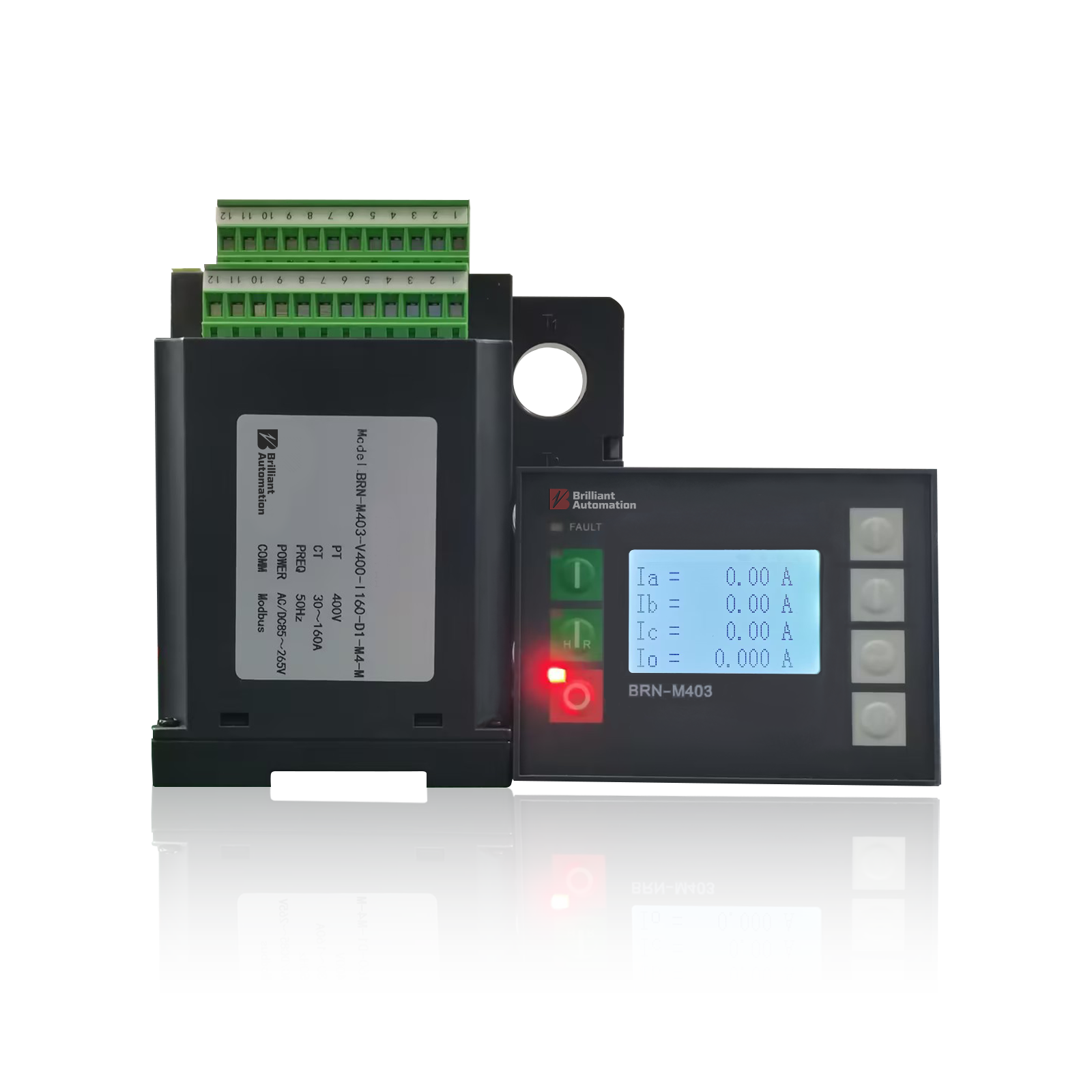
BRN-M403
The BRN-M403 series comprehensive motor protector integrates comprehensive motor protection, real-time monitoring, and multi-protocol communication, making it highly suitable for motor control and protection in industrial automation production lines, pumping stations, fans, compressors, and various low-voltage power distribution systems.
The BRN-M403 series from Shanghai Brilliant Automation Technology is a high-performance comprehensive motor protector, offering a variety of options including basic and dual-speed types. The device utilizes SMT components and high-precision acquisition technology, featuring 0.5-level measurement accuracy and supporting full electrical parameter monitoring (current, voltage, power, unbalance, etc.). It incorporates a refined thermal model algorithm, providing over ten types of protection functions including short circuit, stall, overload, underload, leakage, phase loss, and unbalance, as well as supporting fault recording and self-diagnostics. Additionally, it features flexible I/O expansion (up to 11 digital inputs and 5 relay outputs) and supports communication protocols such as Modbus RTU for remote monitoring. Designed for durability and ease of use, it supports 35mm DIN rail mounting or panel mounting, making it particularly suitable for various industrial sites that require precise motor protection, fault early warning, and intelligent management.
- Measurement Accuracy: Current measurement accuracy Class 0.5; Voltage/Frequency measurement accuracy Class 1.0; Power measurement accuracy Class 1.0.
- Display & Operation: 3.2-inch LCD dot-matrix display; Membrane keypad operation; Multi-language menus; Real-time monitoring of three-phase current, voltage, power, thermal capacity, digital input status, and event records.
- Core Functions: Measurement of full three-phase electrical parameters (three-phase current/voltage, frequency, active power, power factor); Integrated inverse-time thermal model and overload protection; Supports over ten protection functions including short circuit, stall, underload, phase loss, leakage, over/under-voltage, and unbalance; Records for the last 8 trips and alarms; Supports Modbus RTU communication.
- Energy Efficiency & Safety: 35mm standard DIN rail mounting or panel flush mounting; Adopts SMT process and EMC anti-interference design; Supports remote monitoring and fault warnings, ensuring safe and reliable motor operation and reducing equipment damage risks.
Overview
JB/T 10613-2006 is a recommended mechanical industry standard issued by the National Development and Reform Commission of China, officially titled "General technical conditions for digital comprehensive motor protection devices".
IEC 60947-4-1 is an international standard developed by the International Electrotechnical Commission (IEC), designed to provide unified technical specifications and performance requirements for low-voltage electromechanical contactors and motor starters in AC power systems. The BRN-M403 comprehensive motor protector is designed in accordance with this standard to ensure precise and reliable protective actions based on the configured protection logic during motor startup, operation, and fault conditions.
Diagram
Reference wiring and deployment views for installation planning and system integration.
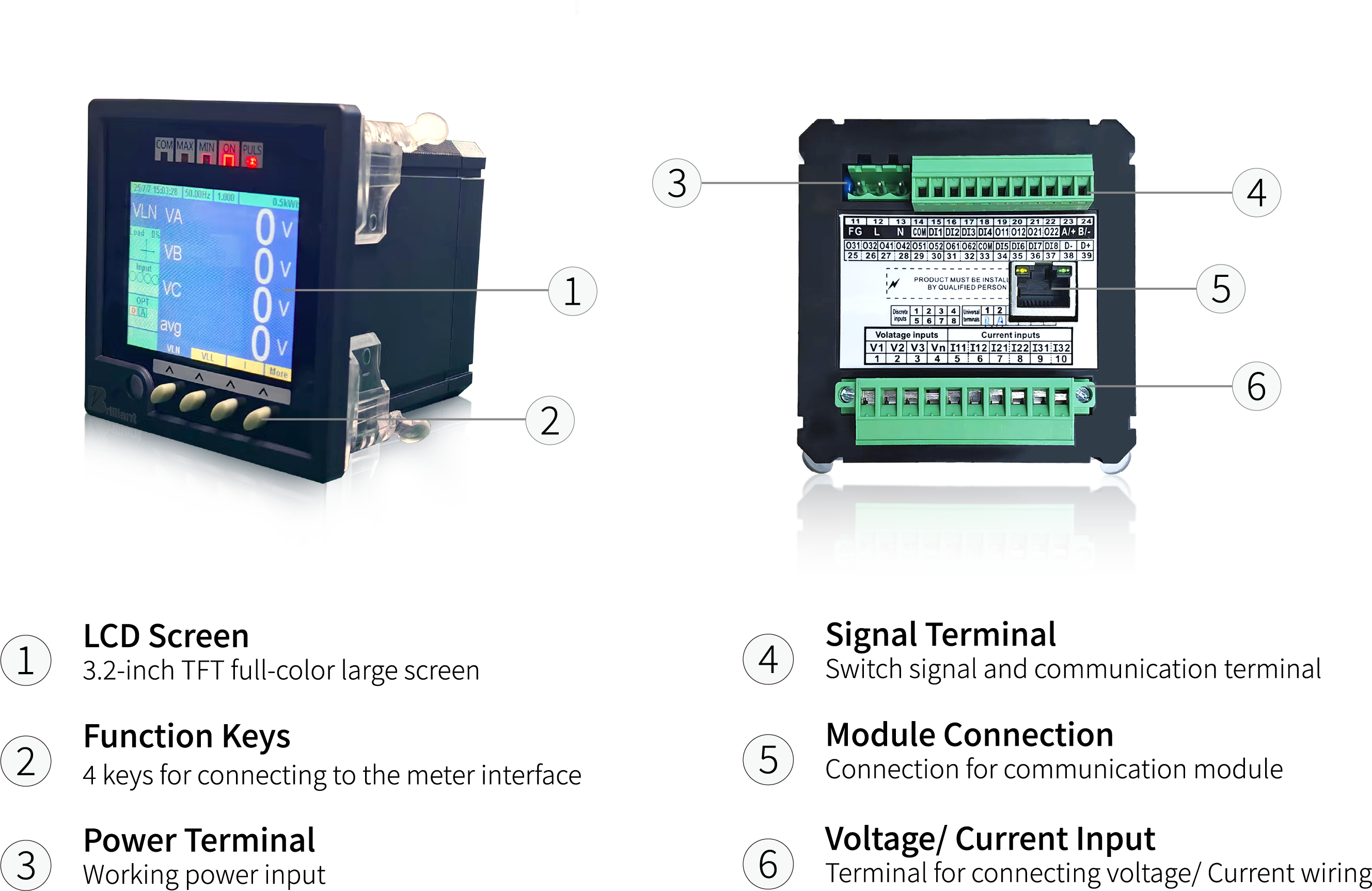
Product Map
Hardware layout reference for interface identification and installation planning.
Key Specs
Core performance highlights for specification review and project planning.
Measurement Accuracy
Provides high-precision measurement of current, voltage, and power for demanding motor and industrial electrical systems.
Intelligent Protection
Supports over ten protection logics including short circuit, stall, overload, underload, phase loss, and unbalance. Features a built-in inverse-time thermal model to enhance system reliability.
Fault Recording & Diagnostics
Records the latest 8 trip/alarm events and their action values to accelerate fault diagnosis, troubleshooting, and post-event review.
System Integration
Integrates with SCADA, PLC, and BMS platforms via industry-standard Modbus RTU communication, enabling remote monitoring and management.
Related Industries
Software workflows for dispatch, forecasting, planning, and grid reliability.




Accessories
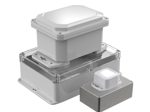
IP66/NEMA 4X Protective Cover
Tailor-made multi-specification protective enclosures for Brilliant industrial equipment. In harsh working conditions involving dust, water splashes, and other contaminants, they are essential. They provide physical protection for internal precision components, elevating the overall protection rating to IP66 or NEMA 4X, ensuring safe and worry-free equipment operation.
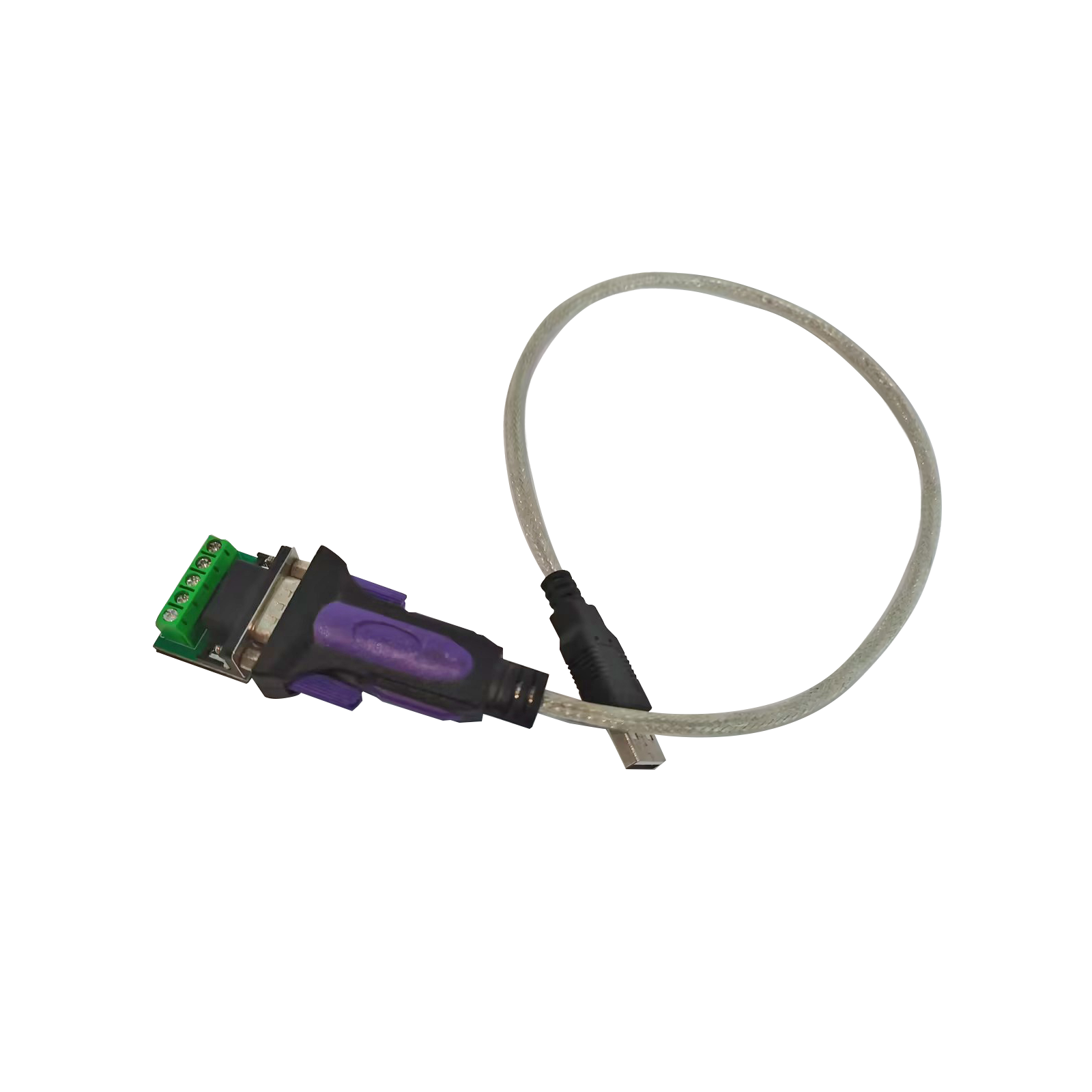
USB-to-RS485 Converter
This plug-and-play USB to Serial RS485 Converter is designed to provide a convenient and reliable connection from Brilliant meters or motor controllers to other devices with a USB port.
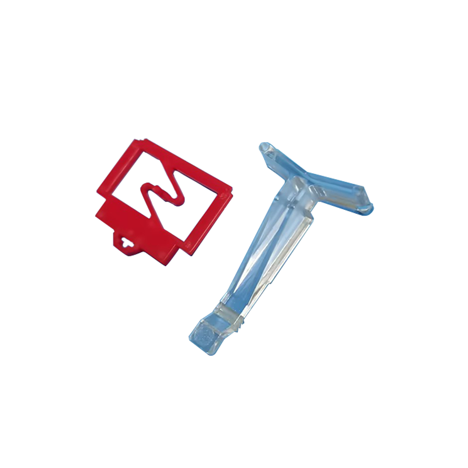
DIN Rail Adapter
The adapter easily secures Brilliant devices onto standard DIN rails. Its transparent locking clip design allows for quick tightening and release, ensuring the instrument or module is held stably and securely in place.
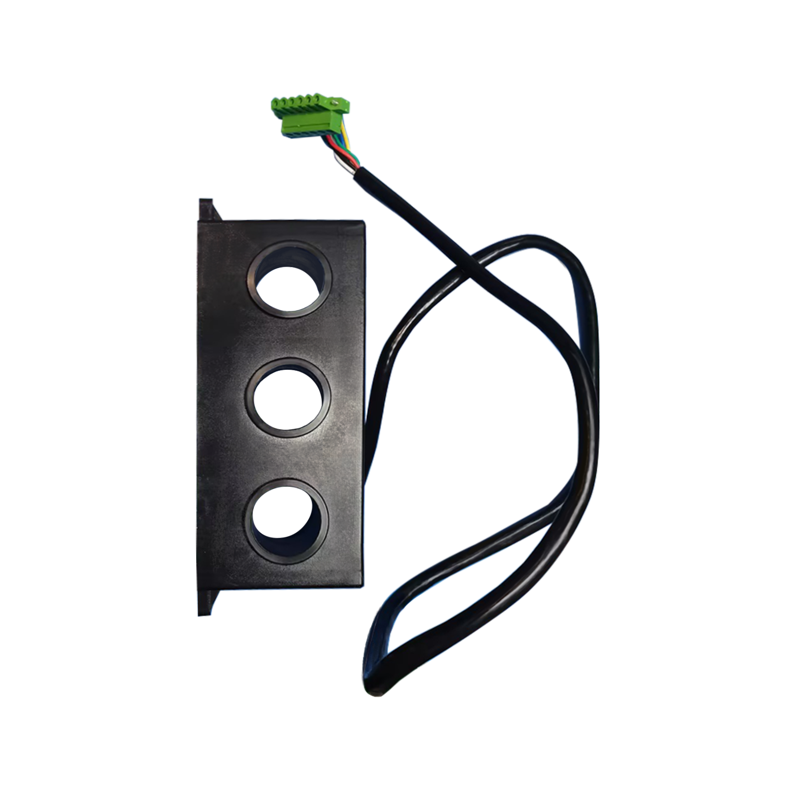
AC Current Transformers
The integrated AC current transformer supports multiple pass-through currents. Designed for the M403 with currents greater than 160A, it accommodates currents up to 250A, 400A, and beyond.
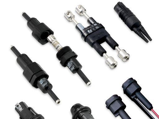
Inline Fuse
In-line fuse holders are used in places with spatial constraints to provide circuit protection in the event of a fault. It is designed to be safe to the touch and flexible for use in different types of applications.
Frequently Asked Questions
Common questions on wiring, setup, and commissioning.
A comprehensive motor protector is an intelligent device based on microprocessor technology that integrates current and voltage detection, multiple protection logics, control, and communication functions. Compared to traditional thermal relays, it not only provides precise overload protection but also offers various protections such as short circuit, stall, phase loss, three-phase unbalance, and leakage, in addition to advanced functions like fault recording, remote communication, and parameter self-diagnostics.
Yes. The M403 panel is equipped with Forward, Reverse, and Stop buttons. After setting the "Panel Control" parameter to "Enable," you can directly control the motor's start and stop via the panel. It also supports remote control through external terminals (X3) to meet the needs of different industrial sites.
Please select based on the motor's rated current and power. For example, motors with a power of up to 75 kW can directly use the built-in through-hole current transformers (available in 1A, 5A, 30A, and 160A specifications); motors with a power greater than 75 kW (i.e., current exceeding 160A) require external current transformers (e.g., 200/5), and the corresponding CT ratio must be set in the device parameters. One thing to note is that, taking the 75 kW motor as an example, the 160A current has a precondition: it applies when the motor's rated voltage is 380V.
Yes, but it is not limited to dual-speed motors. Dual-speed model (M403D): It allows "high-speed current" and "low-speed current" to be set separately in the parameters, and includes a "switching delay" function to meet the precise control and protection requirements of dual-speed motors under different working conditions. Standard default mode: In addition to dual-speed, this series also supports multiple control modes such as direct-on-line starting (standard default), star-delta starting, and forward/reverse operation, which can be optionally configured and set according to the actual motor application scenario.
The basic unit (M403B) supports 35mm standard DIN rail mounting or screw fixing; the operation panel (M403A) requires a cutout (91*67mm) on the cabinet door for flush mounting, achieving up to IP54 protection. The recommended ambient temperature is -20°C to +65°C. It should be installed away from strong interference sources, and control signal wires should be kept as far as possible from the main circuit.
When the current exceeds 160A, an external CT is mandatory. During wiring, the primary cable passes through the external CT, and the secondary side of the external CT (e.g., 5A) is then passed through the M403 main unit (with the 5A specification option). Important: The "CT Ratio" parameter in the device must be set to the external CT's ratio (e.g., 200/5 means setting it to 40); otherwise, the actual current display and protection action values will be incorrect.
The most common error is inconsistent phase sequence between current and voltage. Wiring must strictly follow the manual: Phase A current enters L1 and exits T1, Phase B enters L2 and exits T2, Phase C enters L3 and exits T3; the corresponding voltage terminals must be correct (X1:1 for Phase A, X1:3 for Phase B, X1:5 for Phase C). Incorrect wiring leads to inaccurate power measurement and may cause protection malfunctions.
Rated thermal capacity reflects the heat accumulation of the motor under rated current operation. This value is usually calculated based on the motor's "hot rotor locked time / cold rotor locked time" (typically 15%). It serves as an important baseline for thermal overload protection and should be set according to the technical specifications provided by the motor manufacturer.
If it trips mistakenly during startup, it is usually because the "Start Overlong Protection" delay is set too short. For Star-Delta starting motors, the delay for start overlong protection must be set longer than the Star-Delta transition delay. Furthermore, if the current during startup exceeds the set "Short Circuit" or "Stall" protection values, it will also trip; please check if the settings are reasonable.
The M403 provides a wealth of protection functions, including: Short Circuit, Start Protection (starting overlong), Stall, Overload (inverse-time thermal model), Leakage, Underload, Overvoltage, Undervoltage, Unbalance, and Phase Loss. Among these, short circuit protection is always active; other protections (such as underload and leakage) can be enabled in the parameters (set to non-OFF values) based on actual process requirements.
After a protection trip, to ensure the motor has cooled down, the device typically requires the thermal capacity to cool to a certain level (15%) according to the cooling time constant before allowing a reset. In urgent production situations where a motor that hasn't fully cooled needs to be restarted, the "Forced Reset" option in the panel's main menu can be used to directly clear the thermal capacity memory and release the relay outputs. (Note: This carries a risk of burning the motor and should be used with caution).
It supports the industry-standard Modbus RTU protocol (some models support PROFIBUS). Through the RS485 interface on the device and using shielded twisted pair cables, it can be connected to PLCs, HMIs, or host computers. Up to 32 nodes can be connected on a single bus.
Yes (optional). It provides a 4~20mA or 0~5V analog output. By default, 20mA corresponds to 1.2 times the motor's rated current. You can select whether to transmit Phase Ia, Ib, or Ic current via the "DC Transmit" parameter, making it convenient to connect to DCS systems for real-time monitoring.
After modifying parameters, you must press the ENTER button on the panel to confirm and save. If you press the ESC button to exit, the modifications will be discarded and the device will revert to its original parameters.
1.First, check the "Trip Records" displayed on the panel (up to the most recent 8 records) to identify the cause (e.g., overload, phase loss, short circuit). 2.Address the root cause (e.g., clear mechanical jams, repair lines, restore voltage, etc.). 3.Wait for the motor's thermal capacity to cool naturally, or perform a "Forced Reset." 4.If the cause cannot be identified, check the status of the fault indicator lights in the "Troubleshooting" section of the manual, or read more detailed action values via the communication port.
Request a Quote
Need pricing, lead time, or project recommendations? Submit your inquiry and our team will reply shortly.
Go to Inquiry Form